Logisim Tutorial
Logic Labs | Logisim Tutorial | Lab 1 | Lab 2 | Lab 3 | Lab 4 | Lab 5 | Lab 6
This tutorial walks you through installing, navigating, and troubleshooting Logisim Evolution — the circuit simulator used in all logic lab exercises. Read this before starting any lab.
This tutorial was originally created as a PDF. If you prefer a PDF version, you can download it here: Logisim Tutorial PDF.
Setting Up
1. Download Logisim Evolution
Go to the Logisim Evolution releases page and get the latest .jar file (not the .rpm, .msi, .dmg, or .deb — the plain .jar works on all platforms).
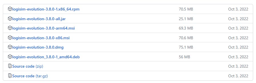
.jar file is the one you want.2. Install Java 16 or Higher
Logisim Evolution requires Java 16 or higher to run. We recommend Adoptium OpenJDK 17.
Windows: Download and run the
.msiinstaller.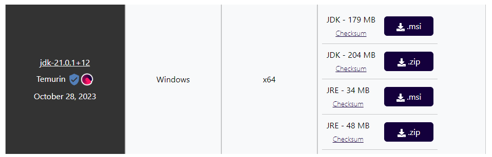
Adoptium OpenJDK download page for Windows — select the .msiinstaller.macOS: Download and run the
.pkginstaller.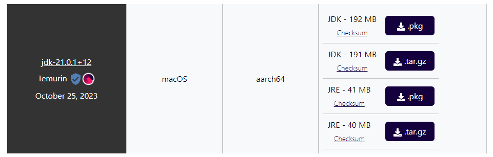
Adoptium OpenJDK download page for macOS — select the .pkginstaller.
3. Run Logisim
Once Java is installed, double-click the downloaded .jar file to launch Logisim Evolution. If your OS warns you about an unrecognized file, you can safely proceed — as long as the JAR came directly from the link above.
Navigating Logisim
When you open Logisim, you will see a toolbar at the top and a component library panel on the left.
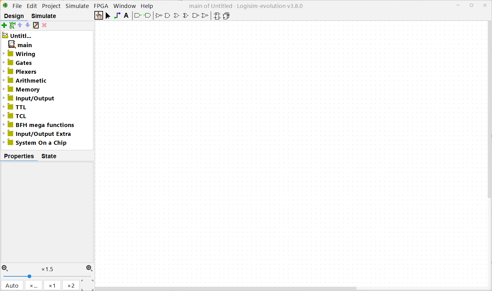
Toolbar: Two Key Tools
| Tool | Purpose |
|---|---|
| Finger pointer (left) | Click circuit elements to toggle their values (0 ↔︎ 1); inspect wire values during simulation |
| Cursor pointer (right) | Move circuit elements around the canvas; draw wire connections |
Remember to switch between these two tools as needed — the cursor tool creates circuits, the finger tool interacts with them.

Component Library
Wiring
Found under the Wiring folder. The four most-used elements are:
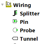
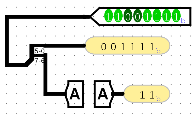
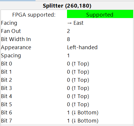
Splitter
Combines or splits wires. Wires in Logisim can represent multiple bits; a splitter lets you break a multi-bit wire into individual (or smaller) groups of bits, or merge them back together.
In multi-bit wires, the MSB (leftmost/highest-numbered bit) is always at the top.
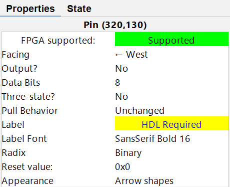
Pin
Introduces inputs to your circuit. Click it with the finger pointer to toggle between 0 and 1. Pins can be configured as input or output pins.
Probe
Reads and displays the current value of any wire in your circuit. Works on multi-bit wires too — useful for debugging.
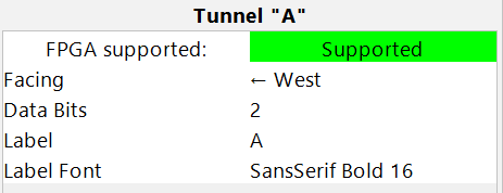
Tunnel
Creates a named “portal” so you can connect two distant points in the circuit without drawing a long wire. Two tunnels with the same name are electrically connected.
Common options (shown in the lower-left Properties panel when a component is selected):
- Data Bits — controls how many bits wide the element’s input/output is.
- Facing — rotates the element to make wiring more concise.
Gates
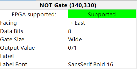
Found under the Gates folder. Standard logic gates (NOT, Buffer, AND, OR, XOR, NAND, NOR, XNOR) are all available.
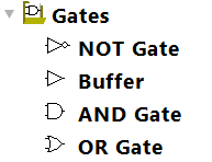
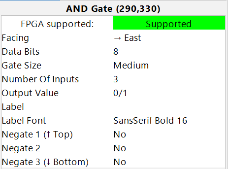
Key options per gate:
- Data Bits — sets the bit width of the gate’s inputs and output.
- Number of Inputs — sets how many inputs the gate has.
Plexers
Found under the Plexers folder. Includes:
- Multiplexer (MUX) — selects one of several inputs based on a select signal.
- Demultiplexer — routes one input to one of several outputs.
- Decoder — activates one output line based on a binary input.
- Priority Encoder, Bit Selector
For a multiplexer, the Select Bits option determines how many select lines there are, which in turn determines the number of data inputs (\(2^{\text{Select Bits}}\) inputs).
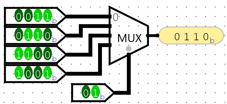
01, the second input (0110) is forwarded to the output.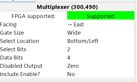
Arithmetic
Found under the Arithmetic folder. Includes ready-made blocks for:
- Adder, Subtractor, Multiplier, Divider, Negator, Comparator
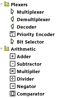
These are useful for higher-level designs without needing to build arithmetic from scratch.
Memory
Found under the Memory folder.
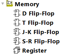
Flip-Flops
D, T, J-K, and S-R flip-flops are available for 1-bit sequential storage. Each requires a 1-bit clock input.
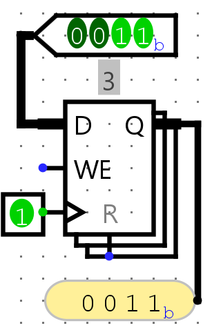
Register
A multi-bit storage element — the most commonly used sequential block in these labs. It captures its input on every positive clock edge (when WE = 1). If WE = 0, it ignores the clock and holds its current value.
The WE (Write Enable) input defaults to 1 when left unconnected.
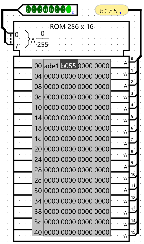
RAM / ROM
Addressable memory blocks. Both the number of address bits and data bits are configurable.
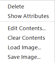
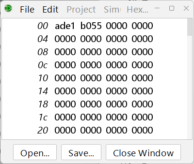
To preset memory contents: right-click the RAM/ROM block → Edit Contents… A hex editor will open. You can also Save the contents to a file and later Load Image… to restore them.
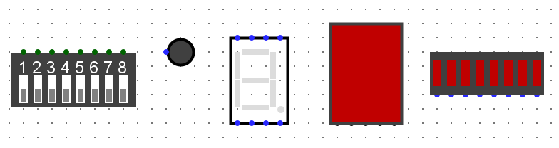
Input/Output
Found under the Input/Output folder. Includes displays, keyboards, buttons, LED arrays, and more. Try connecting logic to these elements to see your circuits come to life.
Debugging Common Problems
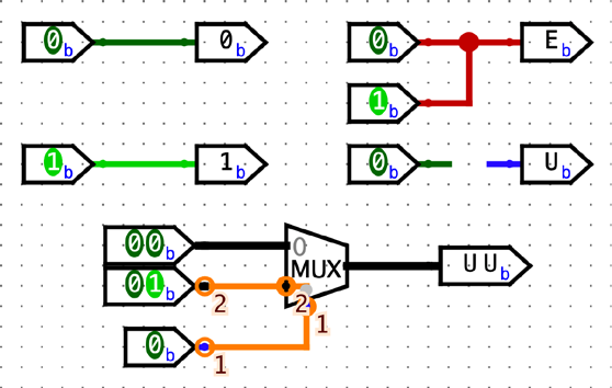
Logisim uses wire color to indicate the state of every connection. If a wire is not green or black, something is wrong — you cannot simulate correctly until all wires are green or black.
| Wire Color | Meaning | How to Fix |
|---|---|---|
| Dark green | 1-bit wire carrying value 0 | ✓ Normal |
| Bright green | 1-bit wire carrying value 1 | ✓ Normal |
| Black | Multi-bit wire | ✓ Normal |
Red (EEEE) |
Double-driver conflict — two outputs are trying to drive the same wire to different values | Remove the extra connection; only one driver per wire |
Blue (uuuu) |
Floating wire — nothing is driving this wire | Connect an output pin, gate output, or input pin to this wire |
| Orange | Width mismatch — wires of two different bit-widths are connected | Make sure both sides of the connection have the same Data Bits setting; check tunnel widths too |
Accessibility: If you have difficulty distinguishing these wire colors, you can customize them via File → Preferences → Simulation Tab.
Red Wires (Double Driver)
A wire can only carry one value (0 or 1) at a time. When two output ports or input pins are connected together — especially if they drive different values — Logisim shows a red wire. Fix this by ensuring only one driver feeds each wire.
Blue Wires (Floating)
A floating wire has no driver. Connect it to an output from a gate, block, register, or an input pin.
Orange Wires (Width Mismatch)
A black (multi-bit) wire cannot connect to a wire of a different width. Check that all connected elements have matching Data Bits settings, and that any tunnels carrying the signal also have the same width.