Module 001: Writing Combinational Logic
Module 001: Writing Combinational Logic
In programming, you often write a sequence of instructions that run in order. In hardware, however, combinational logic evaluates everything at the same time. Verilog models this with the assign keyword and logical/arithmetic operators.
The assign Keyword
The assign statement ties a wire to an expression. Think of it like drawing a wire between logic gates: once defined, it is always true. Note: all assign statements must be done inside the module declaration (within the module ... endmodule declaration).
module simple_and(
    input a,
    input b,
    output y
);
    assign y = a & b; // y will always be the AND of a and b
endmodule
- The value of
yupdates immediately wheneveraorbchanges. You are describing combinational logic here, and the output will always be reevaluated for every change in inputs.
Operators
Verilog supports many operators that can be used for assign statements. Here are the most useful ones at this stage:
Arithmetic
assign sum = a + b; // addition.png)
assign diff = a - b; // subtraction.png)
assign twice = a * 2; // multiply by constant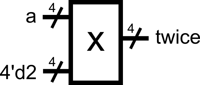
* (multiplication) operator
- This is typically not recommended to be used by beginners for module definitions. This is because a multiplier might not be available for the target hardware implementation. The operator is typically used in testbenches (more on this in Module 0x5) where hardware mapping is not a concern. A typical exercise for beginners is to implement multiplication algorithms using only basic operations to guarantee hardware translation.
Bitwise
assign and_bits = a & b; // bitwise AND.png)
assign or_bits = a | b; // bitwise OR.png)
assign xor_bits = a ^ b; // bitwise XOR.png)
assign not_a = ~a; // bitwise NOT (inverts every bit).png)
If a = 4'b1100 and b = 4'b1010:
a & b = 1000a | b = 1110a ^ b = 0110~a = 0011
Shifts
assign left_shift = a << 1; // shifts left by 1 (like multiply by 2); 0 padding, upper bit(s) truncated.png)
assign right_shift = a >> 2; // shifts right by 2 (like divide by 4); 0 padding, lower bit(s) truncated.png)
If a = 4'b1010:
a << 1 = 0100 (logical shift to the left, upper bit is truncated)a >> 2 = 0010 (logical shift twice to the right, lower bits are truncated)
Conditional (Ternary)
assign max = (a > b) ? a : b;Reads: “If a > b, then max = a; otherwise, max = b.” This is similar to a multiplexer-type behavior, where the selector value depends on the condition inside the parentheses.
.png)
Tip: Assignment upon Declaration
You could actually perform the assignment upon the wire declaration. This skips the additional assign statement for the same signal that was declared.
module example_block (
    input  [7:0] a,
    input  [7:0] b,
    input  op,       // operation selector
    output [7:0] y
);
    // skip the assign statement by directly putting the operation upon the wire declaration    wire [7:0] and8 = a & b;  // bitwise AND
    wire [7:0] or8  = a | b;   // bitwise OR
    assign y = (op) ? and8 : or8;

endmodule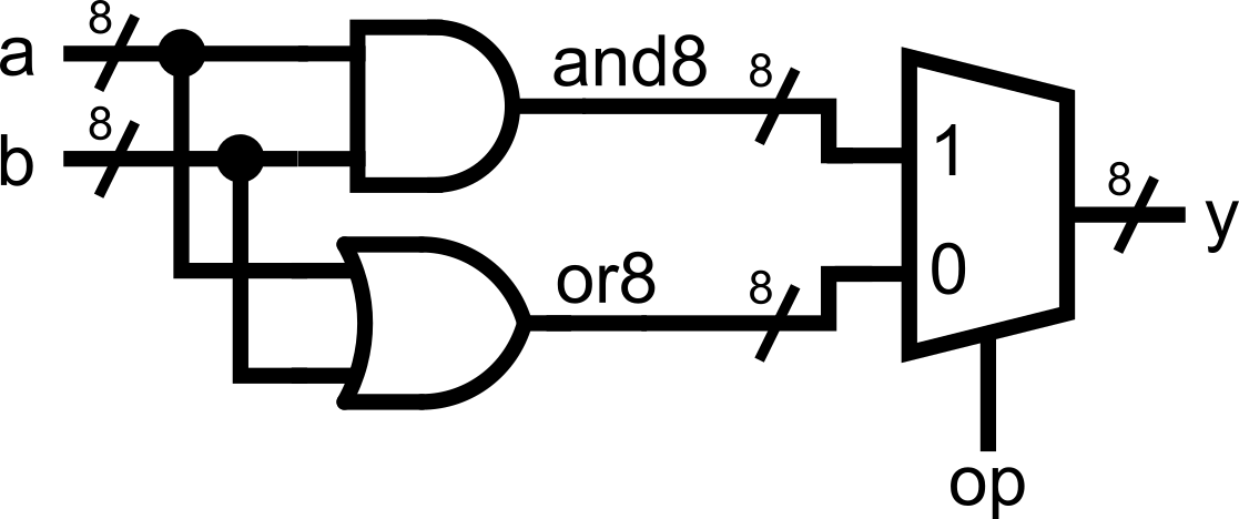
This saves you a line of code per merged assignment. Use your best judgement whether this approach still makes your code readable.
Constants and Number Formats
Verilog allows you to specify numbers in binary, decimal, or hexadecimal with a size. The format is:
<size>'<base><value>'b= binary'd= decimal'h= hexadecimal
Examples:
4'b1010   // 4-bit binary 1010
8'd25     // 8-bit decimal 25, equivalent to 0001 1001 in 8-bit binary (0 padded)
16'hFF // 16-bit hexadecimal FF, equivalent to 0000 0000 1111 1111 in 16-bit binary (0 padded)- If you don’t specify a size, Verilog assumes 32 bits. Typically, when you perform an operation with mismatched widths (for example, a 4-bit vector with a 32-bit constant), the upper bits of the longer vector (in this case, the constant) are truncated. This is usually fine if you know what you are doing. It does not hurt to always declare constant sizes explicitly.
wire [3:0] sum_1, sum_2, a;assign sum_1 = a + 4'b1; // adds 4-bit vector a to 4-bit constant 0001 (0 padded)assign sum_2 = a + 1; // adds 4-bit vector a to 32-bit constant 000...001 (upper bits are truncated during operation)// sum_1 and sum_2 are essentially equalConcatenation, Replication, and Bit Slicing
Concatenation
Verilog provides a powerful {} operator for joining signals together.
wire [3:0] nibble1 = 4'b1010;     // Note: We can perform assignments right on the wire declarations!
wire [3:0] nibble2 = 4'b1100;
wire [7:0] byte;

assign byte = {nibble1, nibble2}; // byte = 10101100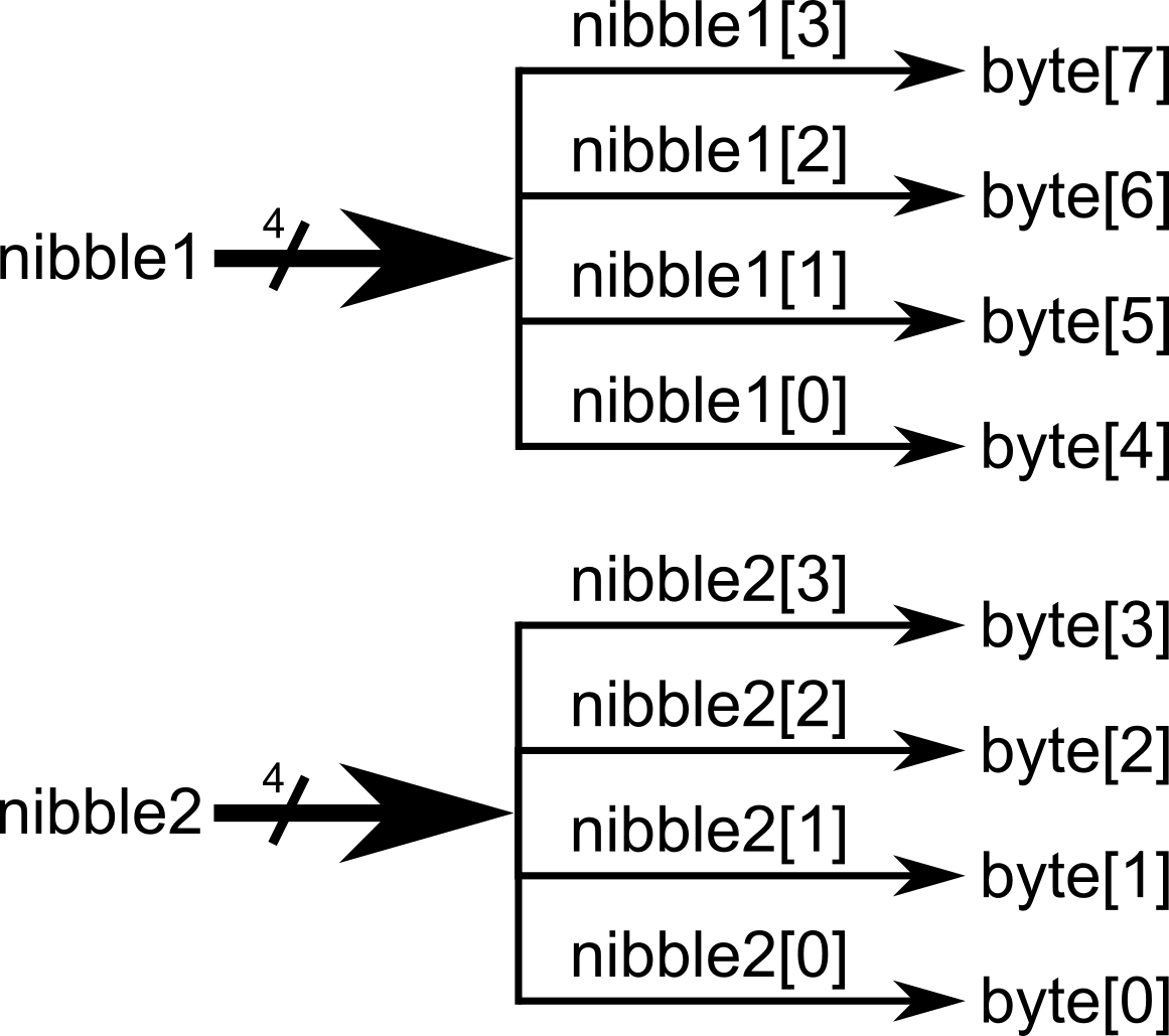
Replication
You can replicate 1-bit signals into several bits using the {multiplier{signal}} syntax. When combined with the concatenation operation from earlier, this is especially helpful for sign-extending vectors (extending/replicating the sign-bit to fix a desired vector length)
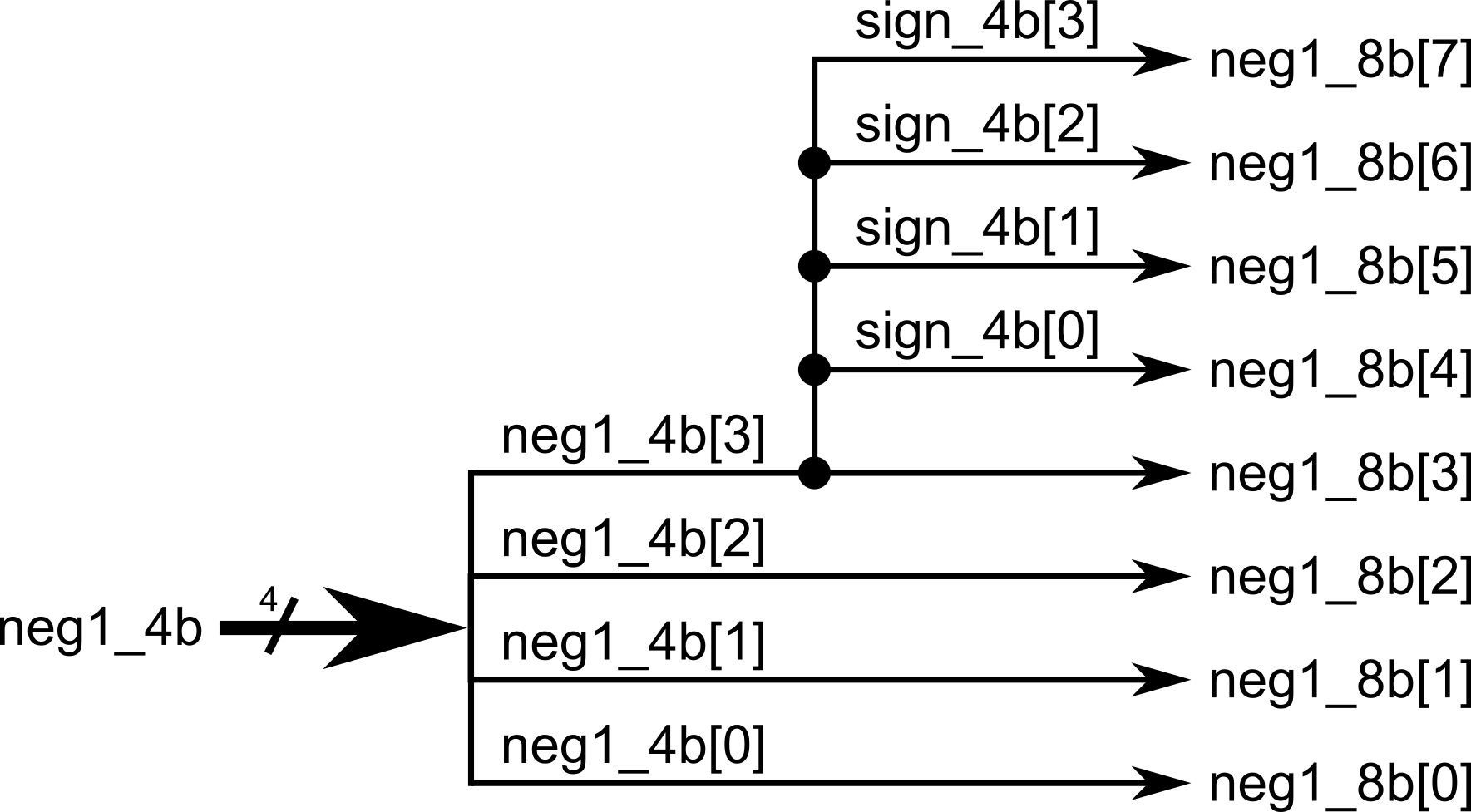
wire [3:0] neg1_4b = 4'b1111;   // -1 in 4-bit twos complement is 1111
wire [7:0] neg1_8b;wire [3:0] sign_4b;

assign sign_4b = {4{neg1_4b[3]}};    // copy the sign bit of neg1_4b, then replicate it 4 times
assign neg1_8b = {sign_4b, neg1_4b}; // concatenate the 4-bit sign with the 4-bit number earlier to make it 8 bits. This is now -1 in 8-bit twos complement.
// Alternatively, you can just perform and concatenation in a single line. Take care of readability!// assign neg1_8b = {{4{neg1_4b[3]}}, neg1_4b};
Bit Slicing
You can also take slices of vectors:
wire [7:0] data = 8'b11011010;

wire [3:0] upper = data[7:4]; // top 4 bits
wire [3:0] lower = data[3:0]; // bottom 4 bits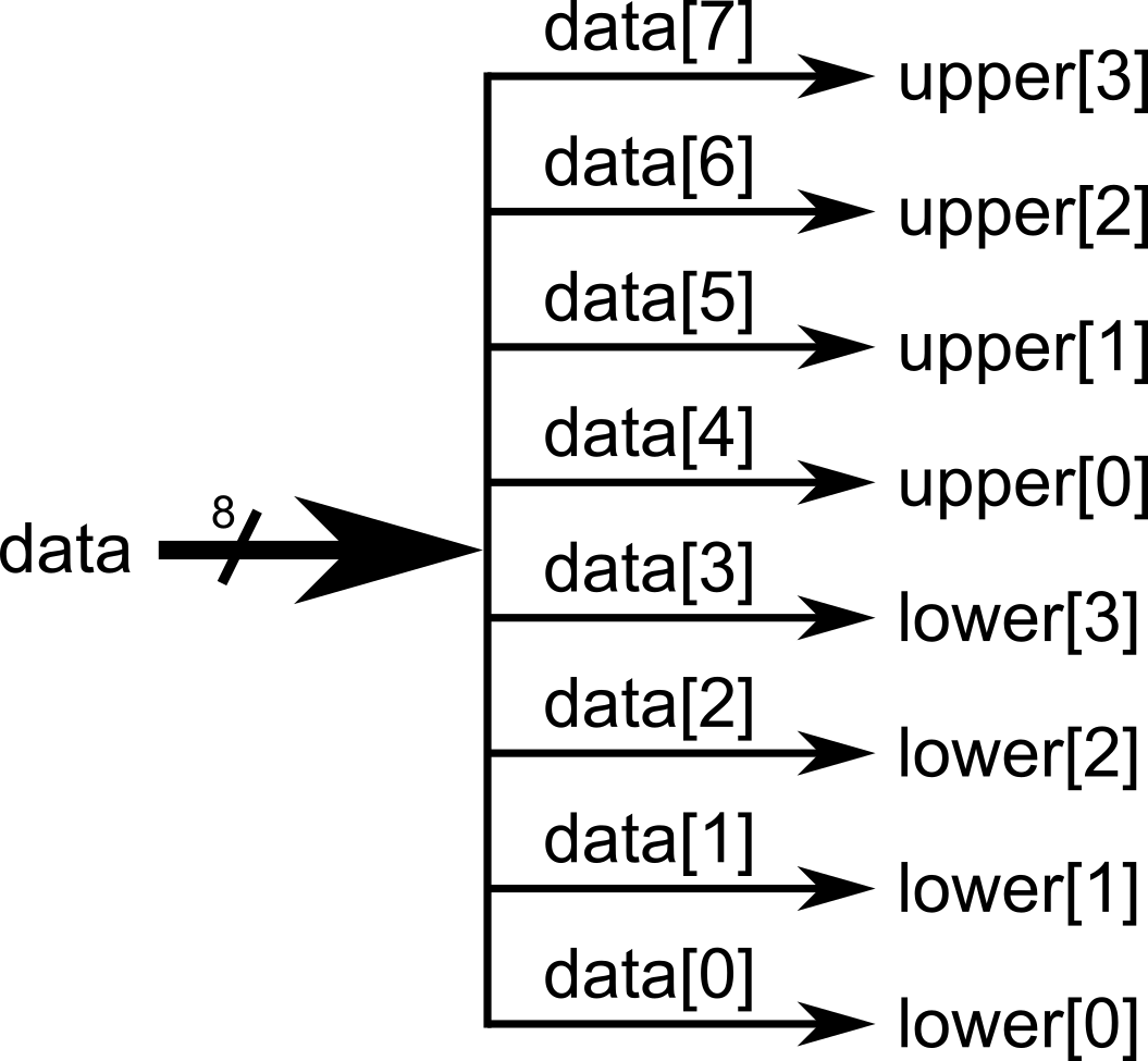
Note: Be careful when assigning between different-width signals.
wire [7:0] wide = 8'b11111010;
wire [3:0] narrow;

assign narrow = wide; // Danger! Mismatched widths. Only the bottom 4 bits are kept in this case: 1010This is legal, but may not be what you intended. Only do so if you know what you are doing. The best practice is to explicitly slice:
assign narrow = wide[3:0]; // intentional truncationImportant Note: Concurrency in Hardware
In software, the order of statements matters. In hardware, multiple assign statements run at the same time. We are essentially describing hardware connections in Verilog, so the order of how we are assigning values to wires should not matter!
Example:
module concurrent_example(
    input a,
    input b,
    output x,
    output y
);
    assign x = a & b;
    assign y = a | b;
endmoduleWhether you write assign x before assign y, or flip them, the hardware is identical. This is the essence of concurrency.
To really see concurrency, let’s make one wire depend on another:
module concurrency_example(
    input a,
    input b,
    output x,
    output y
);
    assign x = a & b;    // x is AND of a and b
    assign y = ~x;       // y is the NOT of x
endmodule
Now here’s the key:
Even though y depends on x, the order of the two assign statements does not matter.
If you swap them:
assign y = ~x;
assign x = a & b;
The result is exactly the same hardware. Both assignments are always active, so y is always the NOT of the AND of a and b.

This is different from software, where order defines execution. In hardware, assignments represent physical connections that exist all at once.
Putting It All Together
Here’s a complete example demonstrating a simple arithmetic and logic unit (ALU), combining everything you have learned so far:
module alu_demo (
    input  [7:0] a,
    input  [7:0] b,
    input  [2:0] op,     // 3-bit operation selector = 8 possible choices
    output [7:0] y       // 8-bit ALU output
);

    // -----------------------------
    // Arithmetic with explicit width extension (to accommodate the carry out without being truncated away)
    // -----------------------------
    wire [8:0] add9;                          // 8-bit number + 8-bit number = 8-bit number with possible carry out (9 bits total)     assign add9 = {1'b0, a} + {1'b0, b};      // zero-extend the operands (making them 9 bits long) through concatenation, add them

    // Remember that for simple assign statements, we can have the wire declaration and assignment in one line.
    wire [7:0] add8 = add9[7:0];              // truncate the 9-bit result and take only the lower 8 bits for the sum.     wire carry_add = add9[8];                 // declare carry_add wire to handle carry out (internal signal only)

    // -----------------------------
    // Bitwise operations and shifts:
    // -----------------------------
    wire [7:0] and8  = a & b;
    wire [7:0] xor8  = a ^ b;
    wire [7:0] or8   = a | b;    wire [7:0] nota  = ~a;

    wire [7:0] shl1  = a << 1;                // left shift (msb discarded)
    wire [7:0] shr1  = a >> 1;                // right shift (lsb discarded)

    // -----------------------------
    // Ternary-based operation selection (a big multiplexer):
    // -----------------------------
    assign y =                                // we can chain the ternary operation together, we can also separate it into multiple lines
        (op == 3'b000) ? add8    :
        (op == 3'b001) ? and8    :
        (op == 3'b010) ? xor8    :
        (op == 3'b011) ? or8     :
        (op == 3'b100) ? nota    :
        (op == 3'b101) ? shl1    :
        (op == 3'b110) ? shr1    :
                          ((a > b) ? a : b);  // we go here if op == 3'b111

endmodule
This Verilog code would have a corresponding hardware equivalent as shown below.
.png)
Our module is getting bigger and more complex! Notice how there are different assignments happening within the single module. All arithmetic and logic were declared, and all of the corresponding outputs would connect to a final multiplexer (declared as a ternary (condition) ? (true) : (false) operation).
Note that all assignments are happening concurrently. We are describing hardware in Verilog, and we are merely describing the interconnections between wires and the logic happening between those wires.
Now you’ve seen:
- How to use
assignto describe combinational logic - Common operators (
+,-,&,|,^,? :,<<,>>) - How to write constants in different formats
- How to concatenate and slice vectors safely
- How concurrency means order of
assigndoesn’t matter
Module Activity : The Assign ALU
This module’s activity is in this Jupyter Notebook. Line by line, you can execute the code in order to see how the environment works. I recommend pressing the Run all button at the top and giving it about 2 minutes to download all of the requirements. In the middle of the notebook, you’ll find a section where you need to fill in some verilog code. Time to show your stuff.
Like in the previous activity, we’ll be implementing an ALU. But this time, NONE OF THE MODULES ARE PROVIDED. Hence, you’ll have to write all the logic yourself using assign statements.
Good luck!