Module 101: Testbench Basics and Verification
Module 101: Testbench Basics and Verification
So far, we’ve been writing synthesizable Verilog — the kind that represents hardware. But before we ever put a design on an FPGA or chip, we must test it in simulation. That’s where testbenches come in.
A testbench is just another Verilog module, but:
- It doesn’t describe hardware.
- It drives inputs and monitors outputs of the design under test.
- It uses special non-synthesizable constructs (like delays and printing) that only exist in simulation.
Basic Testbench Structure
A testbench usually has three parts:
- Design Under Test (DUT) instantiation — we create an instance of our design module.
- Clock generation — a process that toggles
clkso the design can run. - Stimulus and checking — use
initialblocks to provide input values and monitor outputs.
Let’s walk through these step by step.
Timescale
At the top of the testbench file, we write a timescale directive:
This means:
- 1 time unit = 1 nanosecond. We’ll use this to define delays (e.g.,
#10means wait 10 ns). More on this later. - Simulation precision (how granular the logic gate delays would be represented) = 1 picosecond.
Instantiating the Design Under Test (DUT)
For this part, let’s say we want to simulate and verify the multiplication via repeated addition FSM that we have implemented in the previous module.
First, we declare signals for the testbench to drive:
module tb_multiplier;         // module declaration. A testbench does not have explicit input and output ports!
    // declare internal signals that will be used by the testbench    // these are the input and output ports of the design we are planning to test
    reg clk;
    reg reset;
    reg start;
    reg [3:0] a, b;
    wire [7:0] result;
    wire done;

    // Instantiate the design under test (DUT)
    multiplier_fsm uut (
        .clk(clk),
        .reset(reset),
        .start(start),
        .a(a),
        .b(b),
        .result(result),
        .done(done)
);regis used for inputs (since testbench drives them).wireis used for outputs (since DUT drives them).
Clock Generation
We need a free-running clock. We can make one by toggling clk, which was declared as reg, every 5 ns:
initialsetsclk = 0at time 0.always #5togglesclkevery 5 ns. We are using nanoseconds because that is what was defined in the timescale directive earlier.- So the clock period that will be provided to clock our design is 10 ns.
Stimulus with initial begin
To control inputs, we use an initial begin ... end block:
    initial begin
        // Initialize signals
        reset = 1;
        start = 0;
        a = 0;
        b = 0;

        // Hold reset for 20 ns before setting it to 0
        #20 reset = 0;

        // Start multiplication: 3 * 5
        a = 4'd3;
        b = 4'd5;
        start = 1;     // set start to 1
        #10 start = 0; // after 10 ns, set start to 0 (pulse start)

        // Wait for completion by waiting for the posedge of done to happen        // The testbench essentially halts at this point and will only proceed once done becomes 1        @(posedge done);
        // Display result
        $display("3 * 5 = %d (expected 15)", result);

        // Wait for 20ns more then finish simulation
        #20 $finish;
end.png)
#delay: Wait a given amount of simulation time (non-synthesizable). Time units are defined using the timescale directive.$display: Print messages during simulation (likeprintf). This message shows up in the console.$finish: End the simulation.
These are non-synthesizable constructs (i.e., no hardware equivalent).
- You can’t tell the hardware to delay an output at exactly x nanoseconds. Logic gates have delays due to their non-idealities, but you can’t specifically assign a delay for them.
- You can’t tell the hardware to print out messages (where is it going to print out anyway?).
- Hardware always runs. It is a circuit. You can’t just halt it.
They only exist in the simulator, and that is perfectly fine for a testbench.
Putting It All Together
Here’s the complete testbench for the multiplier FSM:
`timescale 1ns/1ps             // timescale directive for time units
module tb_multiplier;          // module declaration. A testbench does not have explicit input and output ports!

    // declare internal signals that will be used by the testbench    // these are the input and output ports of the design we are planning to test    reg clk;
    reg reset;
    reg start;
    reg [3:0] a, b;
    wire [7:0] result;
    wire done;

    // Instantiate DUT
    multiplier_fsm uut (
        .clk(clk),
        .reset(reset),
        .start(start),
        .a(a),
        .b(b),
        .result(result),
        .done(done)
    );

    // Clock generation
    initial clk = 0;
    always #5 clk = ~clk;  // toggle every 5 ns, so 10 ns clock period

    // Test sequence    initial begin
        // Initialize signals
        reset = 1; start = 0; a = 0; b = 0;
        #20 reset = 0; // Hold reset for 20 ns before setting it to 0

        // Start multiplication: 3 * 5
        a = 4'd3; b = 4'd5;
        start = 1;     // set start to 1
        #10 start = 0; // after 10 ns, set start to 0 (pulse start)

        // Wait for completion by waiting for the posedge of done to happen        // The testbench essentially halts at this point and will only proceed once done becomes 1        @(posedge done);        $display("3 * 5 = %d (expected 15)", result); // Display result

        // Wait for 20ns more then finish simulation
        #20 $finish;
    endendmodule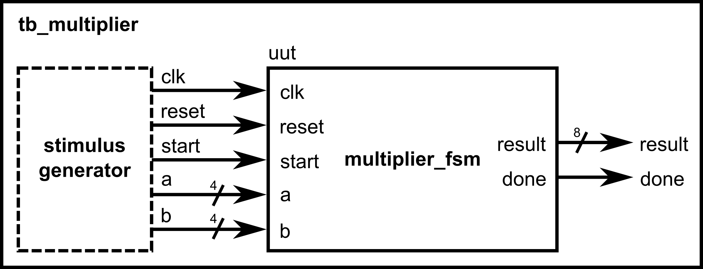
- A testbench is not hardware — it’s a simulation driver.
- Use
initialblocks to define test sequences. - Use
always #delayto make clocks. - Use
$display,$finish,$dumpfile,$dumpvarsfor simulation-only tasks.
Viewing Waveforms
Most simulators let you save signals into a waveform file (like .vcd) that you can view in tools such as GTKWave. For example:
This records all signals so you can open them in a waveform viewer.
Waveforms let you see the step-by-step values of a, b, result, state, and done.
.png)
If you insert the code above into the testbench for the multiplier FSM and run it on a simulator tool, you would see the following waveforms:
.png)
For Verilog simulations using Vivado, you don’t need to add these lines anymore, as Vivado automatically sets up the waveform viewer using your testbench signals.